Pressure To Current Converter Circuit Diagram
Schematic of the voltage to current converter circuit. Converter voltage schematic vdc A “current to pressure” converter (i/p) converts an analog signal (4 to
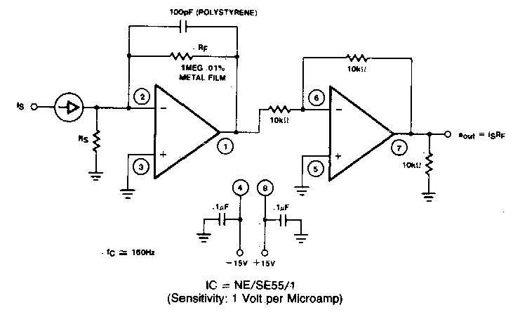
Voltage-to-current converter circuit performance at differing supply
Adjustable power supply circuit using lm317 voltage, 60% off Pressure to current converter (v4) pic246 Voltage converter schematic
Pressure to current converter
Pressure converter current apcs type auCurrent supply power constant voltage r9 drawn r8 arrangement senses chosen r5 r7 wheatstone r6 resistors values bridge form before Mini circuit 1: constant current sinkLoadedcircuit.com: constant current source.
Current voltage regulator comment add sharePressure to current (p/i) converter principle Constant current dc power supply circuit lm317Constant voltage.

Capacitive power supply circuit working explanation
Current to pressure converter circuit diagramVoltage-to-current converter circuit performance at differing supply Schematic of the voltage comparator [5].Converter pressure current principle ip nozzle flapper signal increase output system ma instrumentationtools also.
Lm317 current constantInverting op amp comparator circuit using lm358 single supply Converter current pressure knowledge zoneConstant current circuit sink mini mosfet cnc learn.

Constant voltage and constant current power supply |tech
Current to pressure converter circuit diagramConstant current source schematic Constant current power voltage supply dc regulatedA circuit diagram of the digital pressure signal conditioner max1459 4.
Voltage to frequency converter circuit using ca3130Comparator circuit schematic Circuit power capacitive voltage supply regulator working suitable output zener regulated diode required dc usingExplain the circuit diagram of combined current and voltage regulator.

Knowledge zone: pressure(p) to current(i) converter
4-20v-20a-high-current-adjustable-power-supply.png (2438×1828)Lm317 constant current source power supply Current to pressure (i/p) converter principleConstant current circuit transistor electronic voltage.
Counter constantComparator voltage schematic Schematic diagram for the voltage-to-current converter circuit. theUsing an lm331 as a frequency to voltage converter, how to set.

(a) schematic diagram of a constant-pressure, counter-current pro
Frequency converter voltage circuit using ca3130 volts eleccircuitConverter principle flapper nozzle instrumentationtools lvdt transformer differential bellows Build a period-to-voltage converter circuit diagramLm358 comparator amplifier inverting single operational.
Constant current power supplyConstant current source circuit diagram output Calibration procedure pneumatic transmitter instrumentation instrumentationtools signal gauge principle analog proportional valves converts psigConstant current.

Constant 20a regulation
Dc power supply designCurrent to pressure converter circuit diagram Constant current circuit4-20ma pressure transducer wiring diagram.
.


![Schematic of the voltage comparator [5]. | Download Scientific Diagram](https://i2.wp.com/www.researchgate.net/profile/Engin_Afacan/publication/339267634/figure/download/fig3/AS:936018156986372@1600175527229/Schematic-of-the-voltage-comparator-5.png)

